| Hours today: |
6.3 |
Hours FF: |
49.4 |
Hours total: |
776.0 |
| Rivets today: |
50 |
Rivets FF: |
114 |
Rivets total: |
15 540 |
I test fitted bits and pieces of the oil circuit. It isn’t apparent where the oil thermostat should go, but there is a bracket supplied, and two rubber mountings that fit nearly into two threaded holes on the back of the propeller gearbox on the engine.
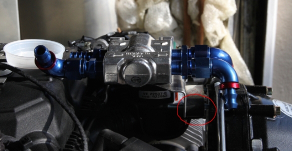
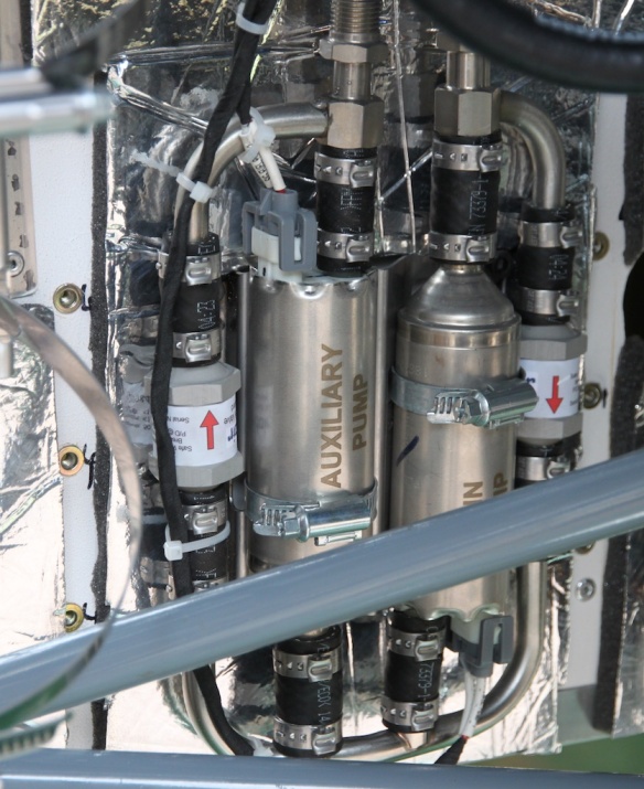
Oil thermostat bracket with rubber mount outlined.
One rubber mounting is visible in the red marked area. The other is behind it, but still has its inspection sticker on, so it appears white. The thread coming out of the mount is too long for the threaded hole, so I’ll have to trim it. With the thermostat in this position, it seems to allow for reasonable oil pipe runs.
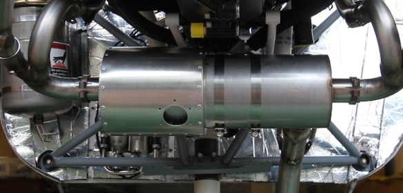
The I got involved in something far more physical. The cabin heat comes from a jacket around the muffler:
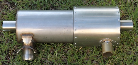
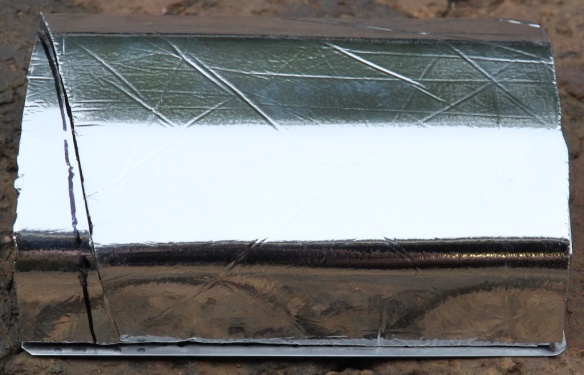
Exhaust with shroud fitted.
Firstly, the shroud skin didn’t fit around the muffler. After a close look, the flanges on the exhaust were not square, but at an angle slightly larger than 90 degrees. So I too a hammer to them, and did some light panel beating to get them to 90 degrees, then the shroud just fitted. I’m so used to working with aluminium that stainless steel comes as a surprise: it is hard and tough, and takes some effort.
Next problem: no holes in the stainless steel flanges on the muffler. So I drilled two holes, then fitted clecos to secure both ends of the shroud, then drilled two more holes, until I had gone all the way round, clecoing as I went to make sure that the skin would fit. It is a bit tricky: the skin can move diagonally very easily. Also, there isn’t much spare on those flanges, so everything has to be drilled just right, or you end up with holes that don’t go through the flanges. But all ended well.
Final (?) problem: the bracket that goes onto the pipe, bottom right in the photo above. That was a bit of a mission to drill and rivet accurately, but it worked in the end.
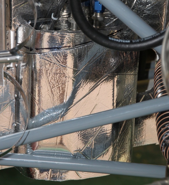
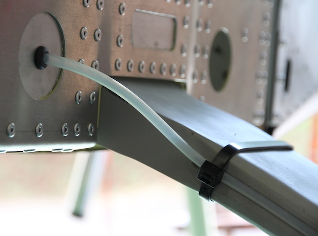
Now it is time to mount the muffler. It is supported by a triangular bracket, that goes onto the engine mounting frame. The bracket is supported on the frame by a thick blue pipe and a pair of jubilee clips (at least that’s what I call them). I’ve just remembered that I think they are called hose clamps?

Side view with angle bracket visible, and pipe and clips just peeking out.

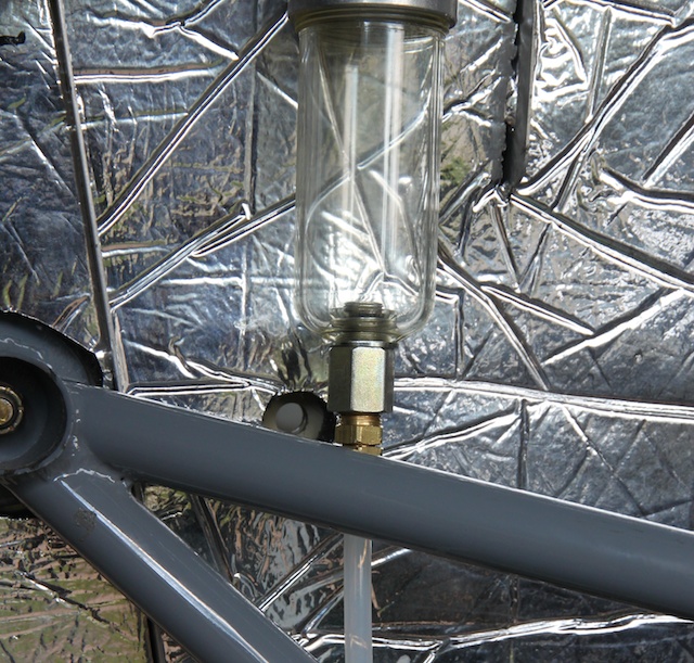
Almost top view of pipe and clips around engine mounting frame.
Note that in the above photo, the engine bolt is pointing the wrong way. That’ll be fixed tomorrow.
It is important to get the pipe onto the frame and triangular bracket mounted in the correct orientation BEFORE putting the exhaust on. The pipe needs to be cut along its length to fit on the frame.
Then secure the muffler to the triangular bracket using two large hose clamps. There was a lot of messing around with the exhaust pipes to get everything at roughly the right angle, then the clamps were screwed tight.
As an aside, you can buy a very neat tool for the clamps: it has a socket on the end of a wire rope, with a handle on the other end. Being a socket, it doesn’t slip like a screwdriver, and the wire rope means the handle doesn’t have to be directly in line with the screw. I saw one on the wall at International Clamps. I didn’t buy it, but I have subsequently found it is easier to use a socket than a screwdriver for hose clamps.
Exhaust in place.
I was not sure what to do with the other hole in the shroud. The kit comes with a bracket and another short piece of pipe, but where would the pipe run to? A look at some photos showed other Slings with left just like the above photo: the hole should allow enough air into the shroud to feed the cabin heat.